Updated for RodDNADesigner Version 1.0 on 24 January 2011
|
RodDNADesigner–
The Bamboo Rod Design
and Analysis Software
Updated for RodDNADesigner Version 1.0 on 24 January 2011 |
| Thank you for using RodDNADesigner. Hopefully this help file will answer all of your questions, but if not, please emal support@RodDNA.com and I will try to personally answer any questions you may have. |
Installation
System Requirements
Windows 95, 98, ME, 2000, XP, Vista, Windows 7, Mac OS X, Linux, Solaris or Unix operating system, 1gb ram or more, 1.0mhz or better processor and a screen resolution of 1024x7680 or better, and a dial-up or faster Internet connection (needed for registration and updates only).
You will need version 1.5.0 or greater of the Sun Java J2SE run-time system to run this version of RodDNADesigner.
To determine the version of Java on you system do the following:
For Windows: click on Start then Run, and type in cmd (or command for Windows 95/98) and press the Enter key.
Now type in: java -version This should display your version of java (if any). If it is version 1.5.0 or greater you can install RodDNADesigner.
To download and install java, please see http://java.sun.com.
Click on the Java SE link on the right, the select the latest Java Runtime Environment (JRE) and follow the installation instructions for your operating system.
For the Macintosh OS X system, please see http://support.apple.com/downloads.
Microsoft Windows Installations
RodDNADesigner can be purchased from various sources including directly on-line from the http://www.HighSierraRods.com web site. You will need approximately 15 megabytes of free disk space on your drive c: for RodDNADesigner and data files. Updates can be automatically loaded via the Setting/Updates menu.
If you have a previous version already installed and you want to save some data see Saving Data Files below.
When downloading the RodDNADesigner_v10.jar file, it should execute the new RodDNADesigner install program. If it does not execute automatically, pick a folder to download the file into that you will remember. When the download is complete, locate the downloaded file (named RodDNADesigner_v10.jar) and double click on it to run the RodDNADesigner installer program. If for some reason the RodDNADesigner_v10.jar does not execute, you can run it directly from a command prompt by typing java -jar RodDNADesigner_v10.jar for Windows and the other operating systems.
This is a self-extracting file that contains the RodDNADesigner installer and program files. Please follow the instructions and please read the license agreement. If you agree with the terms and conditions of the license agreement please continue the installation otherwise please cancel the installation.
Once the installation is complete, you will see the RodDNADesigner Icon on your desktop. Simply double-click on the Icon to launch RodDNADesigner. Note for Linux/Unix/Solais users. You may have to create the program desktop alias/link manually.
RodDNADesigner will be installed in the following location on your default drive (assuming you did not change the default location when you installed it):
For Windows: \RodDNA\RodDNADesigner_v10. For Mac OS X: /Applications/RodDNADesigner_v10. For Linux/Unix/Solaris, please choose the appropriate installation location.
Linux and Unix Installations
Because Linux and Unix versions differ and users of these systems are typically very knotweed, the Windows instructions should suffice.
Previous versions of RodDNA
Because this version of RodDNADesigner does not get installed into the same location as the previous versions, your previous version of RodDNA will not be affected, and you do not need to backup your data files.
Uninstalling
If you decide to uninstall RodDNADesigner, and you want to keep your data files, please copy them to another location on you disk, then simply delete your desktop alias.shortcut and all the files in the installed directory. There are no Windows registry settings to remove.
Registering
Before you can utilize RodDNADesigner, you will need to register on-line, so you will need to be connected to the Internet to do so.
The RodDNADesigner registration dialog will automatically be displayed when you first start the program. You will need your unique serial number that comes with your RodDNADesigner purchase. It is a 39 character serial number that consists of eight groups of 4 characters. When you enter the serial number, you do not enter the hyphens, only the characters in the eight groups of four characters.
Once you enter the serial number and click on the apply button, you can enter your personal data, such as Name, State (if in the United States), Country, EMail address and password. You should enter this data carefully as this information will be embedded in your license file that will be automatically downloaded to your system upon successful registration. In particular, your email address will be used to email you your password in case you forget it.
When have completed entering your data, please click on the Apply button. Once registered, please click on the Done button and RodDNADesigner’s main dialog will be displayed.
Overview
RodDNADesigner is a software application for bamboo rod makers owned and developed by High Sierra Rod Company & Larry Tusoni. It has been designed to run on various computer operating systems including Microsoft’s Windows™, Linux™ and Sun Microsystem’s Solaris™.
RodDNADesigner provides the Rod maker an integrated array of helpful rod-making applications called modules. Each module has a discreet function, but may depend on other modules for some data. The Module’s associated data is saved on the local computer’s disk.
New releases are already being worked on and will be announced via email to current users and announced on the http://www.HighSierraRods.com or http://www.RodDNA.com web sites.
Once you have installed RodDNADesigner, you will need to register. You will need to be connected to the Internet to do so. Please enter valid information, especially your email address and password. Once registered you are ready to start using RodDNADesigner. Your name, city, state and country will be encoded into your program license file so please make sure you enter this information correctly.
RodDNADesigner comes with preloaded files for all modules. You can modify and save you edits using these files.
Many program components, including menus, button, fields, etc. have associated tool tips that indicate the components function. The tool tips are visible when you place the mouse cursor over the component a short time without movement.
Note that the screen images may vary slightly from your RodDNADesigner version.
The information here is intentionally concise, and limited. Please refer to your printed RodDNADesigner documentation.

RodDNADesigner’s main dialog provides access to the Modules, Setting, Accessories and Help. It is a container window frame that contains one or more instantiations of the various program components. This example has the registration dialog displayed.
Modules Menu
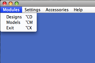
Modules are applications, each providing a distinct function. Two Modules are supplied: Designs and Models. Optional modules may be downloaded and installed to provide additional functionality. You may access them by selecting the menu via your pointer or keyboard using the control key combined with the indicated letter.
The Models Module contains complete rod design information, such as taper values, planing form station increment, bamboo density, etc. Rods are Modeled from Model entries. The easiest way to enter model information (aside from importing) is to enter the tapers using the station increment of your forms (normally 5" increments) in the Values tab table. Once you do so, you can change the station increment to 1" to 12" and the program will automatically calculate the intermediate values. Note that converting back and forth from a given station increment to another may result in less precise values due to rounding. Once you have entered the Models information you can have the program calculate the stresses and chart them as desired. The detailed calculation values can be viewed in the Details tab table and the associated chats can be viewed in the Chart tab charts.This module should be familiar to users of RodDNA.
The Designs Module is completely new and allows you to create and modify taper designs that you can export to the Models Module upon completion. You can easily create a new taper in many different ways, and you can then modify the taper via built-in or custom modifiers.
All designs are for a one piece section or rod. You start by specifying the name, length, line weight, construction (geometry) and value position increment. Generally, it is best to set the value position increment to 5". You can easily change it later to your desired value. For Powell tapers, a 6" value position increment and hex construction is recommended.
Settings Menu Functions
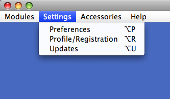
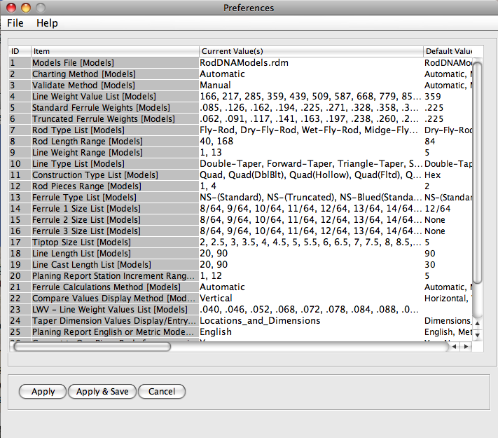
RodDNADesigner can be highly customized by the rod maker. For example, you can: define default values and ranges for most fields; work in Metric or English mode; define default file names for the Module data, etc. The program preferences can be changed (applied) and tested before saved permanently in the program preferences file. Each preference indicates the Module that utilizes the preference.
There are two values per entry that may be edited: the Current Value(s) and the Default Value(s).
The Current Values(s) typically contains the current values that will be used for determining ranges, pull-down list contents, etc. You can reset these values to a default setting at any time by clicking on the Default button when editing.
The Default Value(s) contain the default value that will be used when you create (Insert or Append) a new entry in the Models Module. For example, when you create a new Rod, you either Append it to the bottom of the Rod list or Insert it in front of an existing Rod entry. When it is created, certain fields may contain default entries from the Program Options file.
Profile/Registration
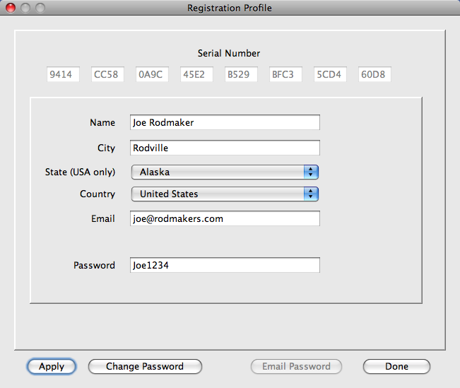
The profile selection allows you to view and edit your on-line registration information. You can update any item except your unique serial number.
Please make sure you have entered your information correctly as it will be encoded into your program license file. Your email address is particularly important as if it is not valid you will not be able to retrieve your password if you forget it.
Here are valid field values (note: allowed special characters will be noted within a set of double quotes):
Serial Number - You should receive a unique serial number when you purchase RodDNADesigner. It should be printed on the book and/or media.
It consists of 32 characters separated by dashes. Please only enter the 8 groups of 4 characters and ignore the dashes. You can use the delete or back-space keys if you enter the characters incorrectly. The serial number can only be registered once, and will be associated with your profile information. You only need to enter the serial number once.
Name -Valid: 2 or more names; letters and special characters " '.-"; 2~50 character length.
City - Valid: letters, numbers and special characters except "~`!@#$%^&*+=}{][;:<>?/\\"; 2~50 character length.
State (USA Only) - If country selected is the United States, you must select a valid home state, otherwise no state should be selected.
Country - Your home country.
Email - Valid: email name @ host; 10~50 character length.
Password - Valid: Any character but must have at least one lower and one uppercase letter and one digit; 6~16 character length.
Updates
The Updates selection allows you to check and install any new RodDNADesigner program updates. You will be informed if any updates have been downloaded, and you will have to close and reload RodDNADesigner for the update to take place.
Accessories Menu Functions
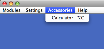
The Accessories menu provides convenient tools that may be useful when designing new tapers. The initial release provides a simple calculator that may come in handy for manual calculations.
Help Menu Functions
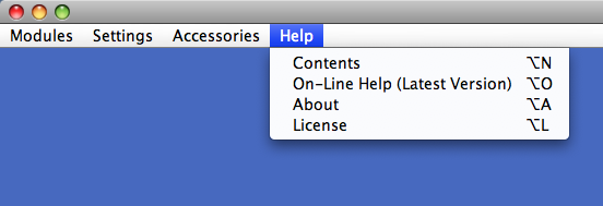
The Contents selection will link to the installed web pages on your computer.
The On-Line selection will link to the latest web pages located on the RodDNADesigner server, so you will have to be connected to the Internet to view it.
The About selection provides system and version information.
The License selection provides your RodDNADesigner license information, which includes the program name, version, your initial registration name and location and the duration of the license. Note that if you update your registration profile, any new information will not be reflected in the existing license file, so it is important to enter your initial registration information correctly.
Modules – Detailed Information
The Designs Module provides the Rod maker the ability to create, modify and analyze tapers in many different ways. This module compliments the Models Module, and together provide an incredibly rich set of rod design tools. For example, tapers are always designed for a one piece section or rod, and are then imported into the Models Module where they can be convert into a resulting Model of some desired line weight, number of sections, etc. Each Design is stored in a discreet file, and many designs can be compared together. Design files can also be created from existing Models.
One of my goals was to make the taper design process as simple as possible, requiring the absolute minimum of data. Another equally important design goal was to provide the ability to step forward and backward as you modify your tapers. This way, you can easily try some modification, and if you don't like the results, you can simply step back to the previous state of your taper.
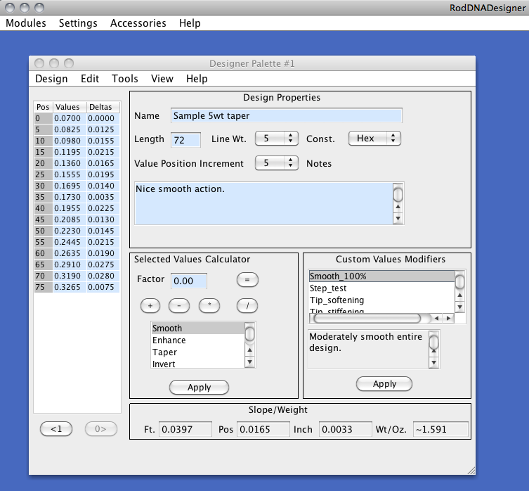
As you can see in the main RodDNADesigner dialog, there are very few parameters. You only need to specify the length, desired line weight, construction type and the value position increment (station increment). Note that these values will be saved and restored automatically for your convenience. Optionally, you may enter a name and notes. Once you have accomplished this, you can then create a new taper.
Position/Values/Deltas Table
This table allows you to enter taper values manually. To manually enter a taper values, simply select the value and edit it. A new feature is the ability to edit the Delta values. You can also utilize the Values Editor described later. You can select one or more values or deltas on which you can apply one of the built-in modifiers, or adjust via the calculator. You can also select a sub-sequence of values upon which you can create a new taper vs. creating a new taper for all the values.
Selected Values Calculator
This frame allows you to adjust one or more selected values or deltas. Lets say you have hollowed the butt sections of a design and you want to increase the dimensions by 3% to compensate for the hollowing. You can simply select the range of values of the part that will be hollowed, then enter 1.03 into the Factor text field and click on the * button (multiply). This will increase the selected values by +3%. You may also select a section which you would like to smooth by simply by selecting the Smooth modifier and clicking on the apply button.
Custom Values Modifiers
This frame allows you to adjust predetermined sections of a design by applying one or more custom modifiers. Custom modifiers are intended to make the task of routine adjustment of taper values easy and repeatable. Some custom modifiers will be supplied with RodDNADesigner, you may find them useful as-is or can modify them from the Tools menu described later. One good example might be the ability to provide tippet protection (typically reducing the dimension by some small percentage for the tip of the rod). You can simply select a tippet protection custom modifier and click on the Apply button.
Slope / Weight Information
The designs slope is calculated for one foot, value position and inch for your convenience. Also, the design section Bamboo weigh is estimated in ounces.
Designs Module Menus
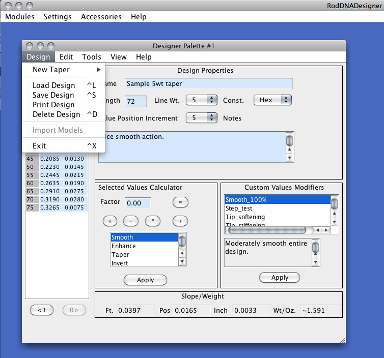
The Design Menu allows you to create, load, import, print, delete or save a design, or exit the Designer Module. Note that like any module, multiple instances of Designer Modules may be opened at a given time making it easy to work on multiple designs at once.
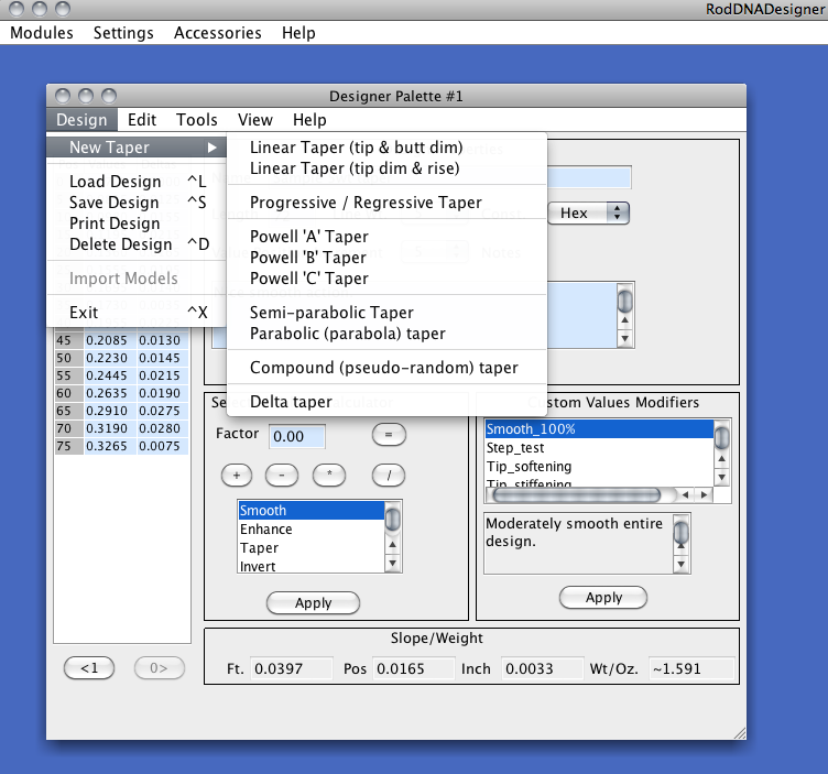
The New Taper sub-menu allows you to create a new taper for your entire design length or sub-sequence. You can create two types of liner tapers, a progressive or regressive taper, the three Powell tapers, Semi and Parabolic tapers, compound (pseudo-random) tapers or Delta tapers. You can also create a new averaged taper from the Edit Menu described later.
Generally, you select the desired taper type, enter the parameters and select the Calculate button. If you are satisfied with the calculated slope values, simply click on the Apply button to load the new taper, if you, you can enter new parameters and try again.
It is beyond the scope of this document to describe the details of each specific taper type and all the implications. Please refer to your printed documentation.
The Import Models option allows you to automatically create designs from existing Models from the Models Module. From the Models Module, simple select one or more models, then select the Import Models from this menu. This is an easy way to create a design of a model that you want to modify.
The Edit Menu allows you to traverse to previous or subsequent design states, copy and paste taper values and models and select or deselect values. Note that I have also added two small buttons on the bottom left that provide the same functions and also indicate how many states or levels you can step in either direction.
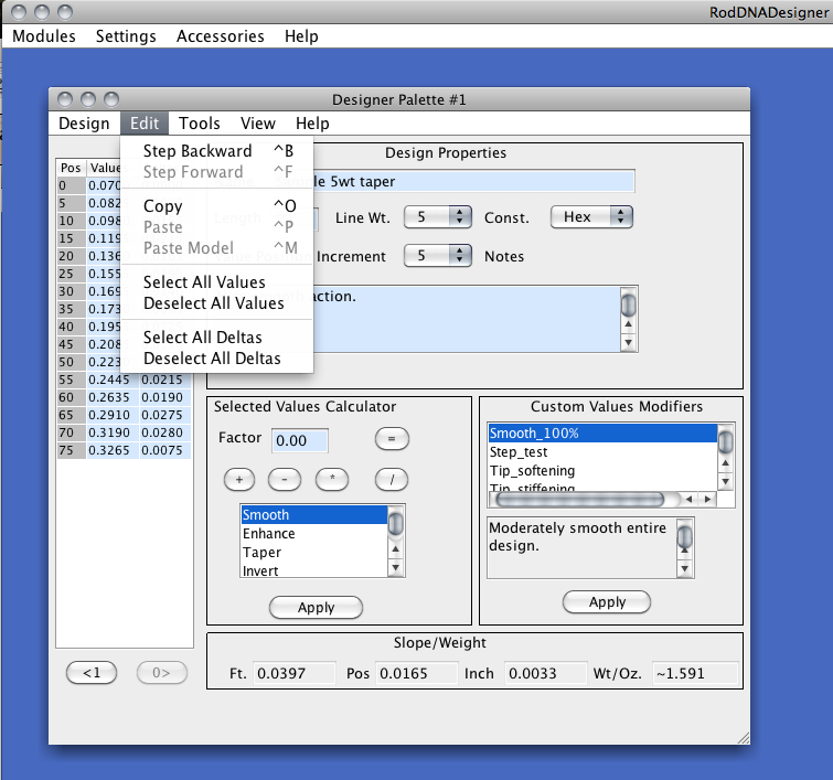
Step Backward / Forward
Every time you edit your design the previous design state is saved. You can then step backwards and forwards seeing all your design changes or design states, and select the design state you desire. This is sometimes called Undo and Redo and is usually available in image editing software programs. This feature make it easy undo undesired modifiers or modifications.
Copy / Paste
The Copy and Paste commands allow you to copy design and model data from one Module to another. You can copy your current design and paste it into either another Design Module or Append Paste Design into a Models Module as a new model. This is how you convert a design to a model.
To copy a design from one Design Module to another, simple select Copy from one and select Paste in the other. To copy a design from a Design Module to a Models Module, select Copy from the Design Module and select Append Paste Design in the Models Module.
Paste Model
This command not only allows you to paste a copied model from a Models Module into a Design Module as a new design, it also allows you to create a new averaged taper from two or more copied models from a Models Module!
To copy a model from a Models Module to a Design Module, simply select a model from a Models Module, the select Copy for Designer from the Edit Menu. Now you can select Paste Model from the Design Module's Edit Menu.
To copy an average of two or more selected models (i.e. create a new averaged taper), select two or more models from a Models Module, then select Copy for Designer from the Edit Menu, then from a Design Module, select Paste Models Average from the Edit Menu.
Tools Menu
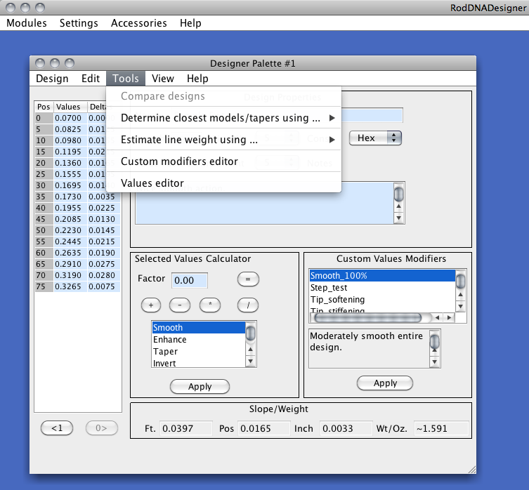
This menu allows you to analyze your design or designs, edit or enter taper values on off-positions and create custom modifiers.
Compare Designs
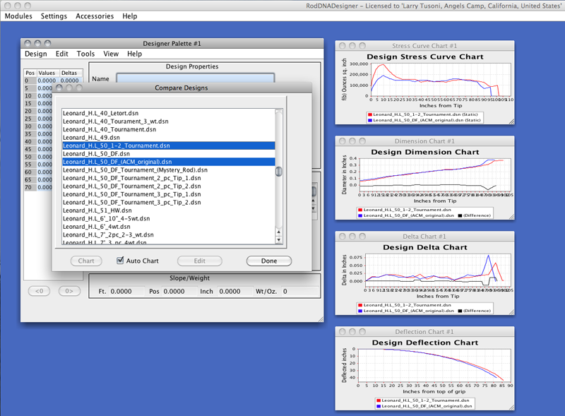
The Compare designs selection allows you to visually compare two or more designs from existing design files. You select the designs to compare and the display charts will be updated with the charted data. Note that you must have at least one chart visible. You can view one or more of the following: Stresses, dimensions, deltas and deflections. When comparing exactly two designs, the difference will be displayed in the dimension and delta charts.
Determining Closest Models
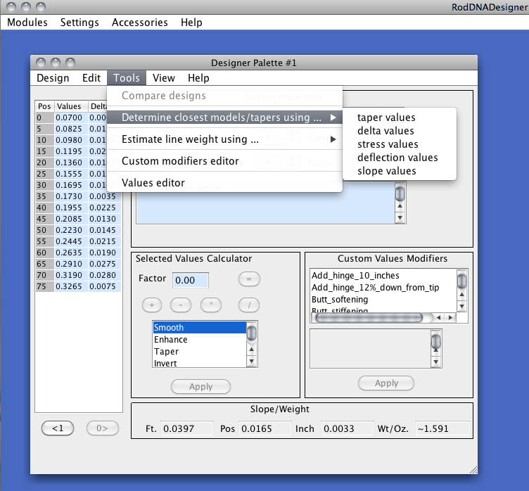
Once you create a new taper you might want to see if it is indeed somewhat unique. RodDNADesigner has the ability to compare a given design's set of values to all models in the Models Module database using various correlation algorithms vs. simple numerical comparisons. The 12 top matches will be automatically selected and displayed with their associated matching % values. You may find the results interesting. You can specify how many results to pick and if you wan to consider rods of different lengths via setting in the preferences menu. Your can use taper values, delta values, stress values, deflection values or slope values.
Here is an example. I created a new Compound (pseudo-random) taper, then found the top matches using the taper values. You can see that the top three matches are not exact matches, but do correlate reasonably well.
Estimating Line Weight
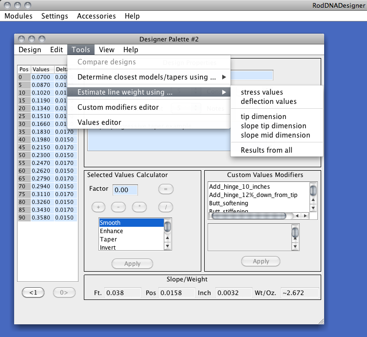
When you create a new taper, you only estimate the line weight desired, the specified line weight is not factored in. Therefore, five simple methods of determining line weight of a taper are provided.
A very simple method is to use only the tip dimension. There is an entry in the Preferences that indicate tip dimensions for each line weight. You can customize this for your purposes. The design's tip dimension is compared to these values, and the closest match determines the approximate line weight.
A more sophisticated method is to use static stresses to determine the approximate line weight. The Design's static stresses are calculated while altering the line weight until the closest match to the Max Stress parameter that can be set in the preferences.
Similarly, you can use use a deflection to determine the approximate line weight. The Design's deflections are calculated while altering the line weight until the closest match to the Max Deflection parameter that can be set in the preferences.
Additionally, you can use the design's slope tip or mid value ranges. These values can also be customized in the preferences.
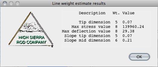
Note that determining line weight is difficult and depends on many factors especially the type of taper, so don't be surprised if you see results that don't all indicate the same line weight. Here are the results from a random taper I created that appears to me to be a good 5 weight taper. The dialog indicates the type of line weight determination, the estimated line weight and the value of the design used.
Custom Value Modifiers
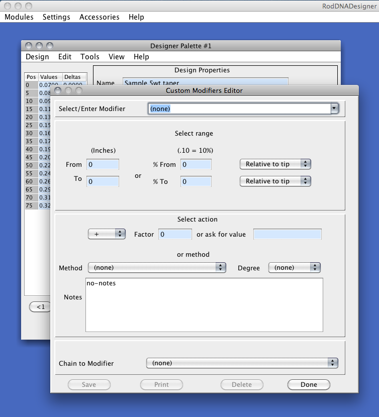
Once you create a new taper you may want to adjust it in one or more ways on a consistent basis. For example, you may want to always provide tippet protection, a swell for the butt, smooth the taper of a section, increase the area that will be hollowed, etc. You can do all of these using the Selected Values Calculator and the built-in modifiers, but you will have to select the values and apply the calculator or built-in modifiers manually.
Alternatively, you can create Custom Modifiers that you can use over and over. Some examples come with RodDNADesigner and can be used as-is or modified to your liking.
Each Custom Modifier has a name, a range and an action or method. Optionally, you many enter some Notes that will be displayed in the Designer dialog. The name should descriptive and indicate what the modifier is intended to do.
The range is the contiguous set of taper values that the modifier will affect. You may specify this range in may ways. For example, you can explicitly state the beginning and end in inches or you can specify a relative range using a percent values. The from and to range values can be relative to either the tip or butt of the design. (Note that 0% is indicated by .0 and 100% is indicated as 1.0)
You then specify either an Action or select a Method. For an Action, you can specify the calculator function or boolean operator to be performed, and either enter the Factor or enter a name for the Factor and have it entered every time the modifier is executed. All this may initially sound complicated, but once you view some of the supplied examples you will see how easy Custom Modifiers are to create, and how powerful they are.
If you have two or more Custom Modifiers that you routinely use together, you can Chain one to the other so that you only need to apply the first one and the other, chained modifiers will also be applied. Note that if you create an infinite chain the program will warn you.
There are many more options available which are described in the printed documentation.
Values Editor
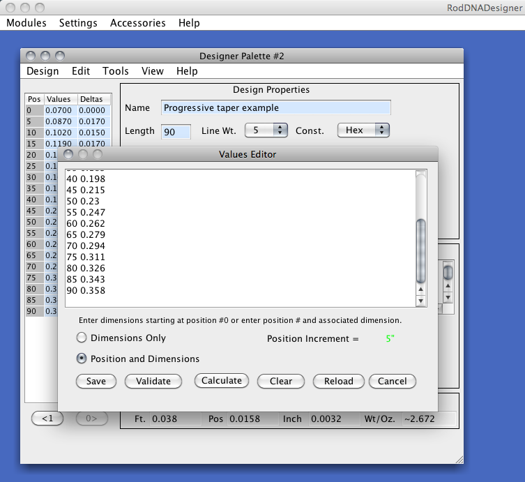
The Values Editor allows you to enter taper values with or without the associated position increments. You can also paste in taper values that you have copied from a text file, email, etc. by selecting the Clear button, clicking on the taper values text box, then pasting the values using Ctrl-V on Windows or Apple-V on a Mac.
Another powerful feature is the ability to enter partial tapers values. For example, you might want to take a taper from a classic rod and you can't take measurements under the wraps, ferrules etc. the Values Editor allows you to enter intermediate values and will calculate the missing values automatically. You might then use the Selected Value Calculator to reduce the dimensions by -.003 ~ -.006 or so due to the varnish.
View Menu
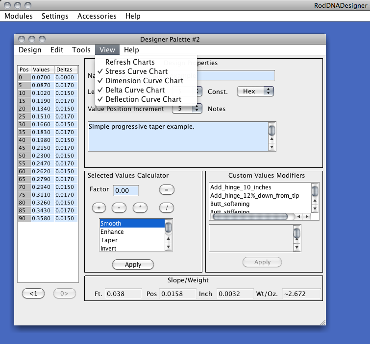
The View Menu allows you to enable the various charts associated with your design. Simple click on a chart entry and you will toggle it on or off. The refresh option is helpful when the charts are obscured by another dialog.
The charts will be described later.
Help Menu
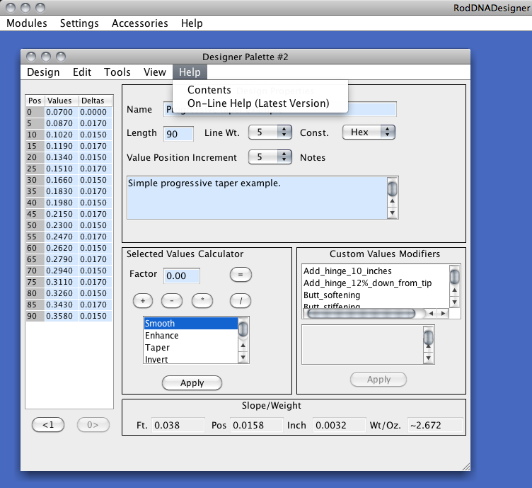
The Contents selection will link to the installed web pages on your computer.
The On-Line selection will link to the latest web pages located on the RodDNADesigner server, so you will have to be connected to the Internet to view it.
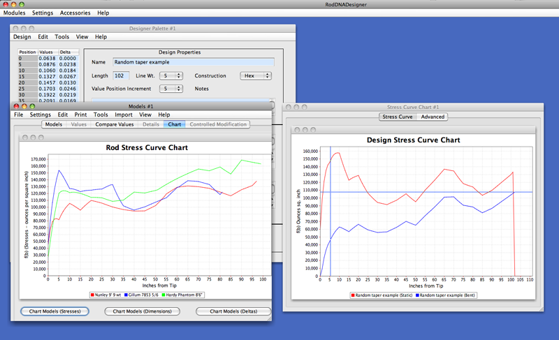
Charts
RodDNADesigner provides four charts to aid in taper design:
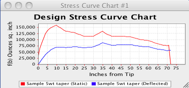
The Design Stress Curve Chart shows a graph of your current design's static and deflected stress values, indicating ounces of stress per square inch for each inch of your taper.
You may already be familiar with the Garrison static stress curve which has been always been available in all incarnations of RodDNA.
to this we calculate the deflected (loaded rod) stress values also.
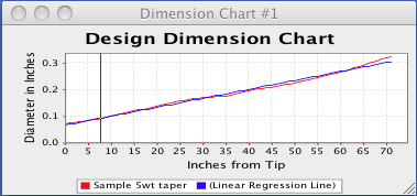
The Design Dimension Chart shows a graph of your current design's taper values in inches from the tip to the end of the section/rod.
The Linear Regression Line is calculated to help you see how the taper values deviate.
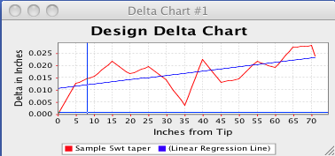
The Design Delta Chart shows a graph of your current design's delta values in inches from the tip to the end of the section/rod.
The Linear Regression Line is calculated to help you see how the delta values deviate. Delta values are the differences from a given taper value from the previous.

The Design Deflection Chart shows a graph of your current design's deflected values in inches from the tip to the end of the section/rod.
The Linear Regression Line is calculated to help you see how the deflected values deviate.
This chart may be familiar to those of you who use or used a physical Deflection Board to determine a rods action.
Please refer to your printed documentation for more detailed information on all the charts.
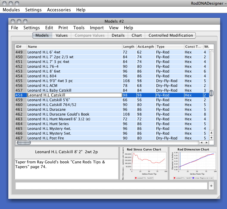
The Models Module provides the Rod maker will all the data and tools necessary to modify any of the hundreds of rod models contained in the models database. They models consist not only of tapers, but all the associated rod adornments, ancillary information, etc. Each model can be modified in many ways. New models can also be added.
Fields
Each row represents a Model. Each row contains many columns or fields. Fields may contain alphanumeric, numeric or pull-down lists of predetermined values.
Note that you may sort the Models by clicking on one of the field headings. You can also sort on another, secondary field by using the Control key before clicking on the field heading. You will be asked to save the sort state before you can access the sorted Model list.
When you do, only the list of Models in your computer's memory will be sorted. You can always save the newly sorted list to a file using the File Save or File Save as menu options.
The fields are as follows:
|
ID# |
This is a program generated field indicating the number of the Model or row. |
|
Name |
The unique name of the particular Model. |
|
LengthInch |
The rod length in inches. The length range is defined in the Program Options field Rod Length Range. Changing this value will automatically adjust the ferrule locations and sizes. |
|
ActLngInch |
The rod’s action length (usually LengthInch -10"). The length range is defined in the Program Options field Rod Length Range. |
|
Const Type |
This is the construction type of the rod, typically hex or six sided. The values are defined in the Program Options field Construction Type List. Changing the Construction Type may generate a new model. See the Automatically Generated Models section for more information. |
|
Wt. |
The line weight of the rod. . The weight range is defined in the Program Options field Line Weight Range (Not the Line Weight Value List) |
|
Line Ft. |
This is the physical length of the given line. . The line length range is defined in the Program Options field Line Length Range. |
|
Cast Ft. |
This is the casting length of the given line. . The line length range is defined in the Program Options field Line Cast Length Range. |
|
Pc. |
The rod’s number of pieces. The rod pieces range is defined in the Program Options field Rod Pieces Range. Changing this value will automatically adjust the ferrule locations and sizes any may generate a new model. See the Automatically Generated Models section for more information. |
|
F1Size |
The size of the first ferrule in 64th inch. The ferrule size list is defined in the Program Options field Ferrule1 Size List. This can be automatically calculated by the program or manually entered. |
|
F2Size |
The size of the second ferrule in 64th inch. The ferrule size list is defined in the Program Options field Ferrule2 Size List. This can be automatically calculated by the program or manually entered. |
|
F3Size |
The size of the third ferrule in 64th inch. The ferrule size list is defined in the Program Options field Ferrule3 Size List. This can be automatically calculated by the program or manually entered. |
|
Ferrule Type |
The type of ferrules used. The ferrule type list is defined in the Program Options field FerruleType List. |
|
F1Location |
The location of the first ferrule. This can be automatically calculated by the program or manually entered. |
|
F2Location |
The location of the second ferrule. This can be automatically calculated by the program or manually entered. |
|
F3Location |
The location of the third ferrule. This can be automatically calculated by the program or manually entered. |
| Tip Top Size | The size of the Models tip top guide. |
| LWV | The Line Weight Value from Controlled Modification |
| RAV | The Rod Action Value from Controlled Modification |
|
ImpactFactor |
The Impact Factor Multiplier. Normally set to 4 but can be varied as desired. |
|
Bamboo |
The weight of the Bamboo per cubic inch. Normally set to 0.668 .oz/cu in. but can be varied as desired. |
|
Tip Weight |
The weight of the Tip Top. Normally set to 0.018 .oz but can be varied as desired (this has a minimal effect on the moment calculations) |
|
StationMul |
Multiplier used in calculating the planing form values. |
|
StationBias |
+/- amount used to adjust the planing form values. |
|
StationIncr |
The Station Increment of your taper/stress values which normally corresponds to the station increments on your planing forms. Values from 1" to 12" can be specified. |
|
Notes |
Comments & Notes about the model. |
|
Dimensions |
The Model’s dimension values at StationIncr increments. Edited via the Values tab or by the Values Editor dialog, which is accessed via the Values tab. Note that you can paste a comma separated list of values in this field vs. entering them via the Values tab. |
|
Stresses |
The Model’s stress values at StationIncr increments. Edited via the Values tab or the grid. Note that you can paste a comma separated list of values in this field vs. entering them via the Values tab. |
| Guide Spacings | The Model's guide spacings. Note that you can paste a comma separated list of values in this field vs. entering them via the Values tab. |
| Guide Sizes | The Model's guide sizes. Note that you can paste a comma separated list of values in this field vs. entering them via the Values tab. |
Tabs
There are currently six tabs available:
The Models Tab is the main tab, and is used to view/enter/edit Model data except for the Dimension or Stress values.
The Stresses & Dimensions thumbnail charts are automatically rendered when you select at least one Model or row. Since the detailed calculation values are not saved, the calculations need to be performed before the charts can be rendered and thus can take a few seconds on a slow computer. If you like, you can select Automatic or Manual charting via the Program Options Charting Method option.
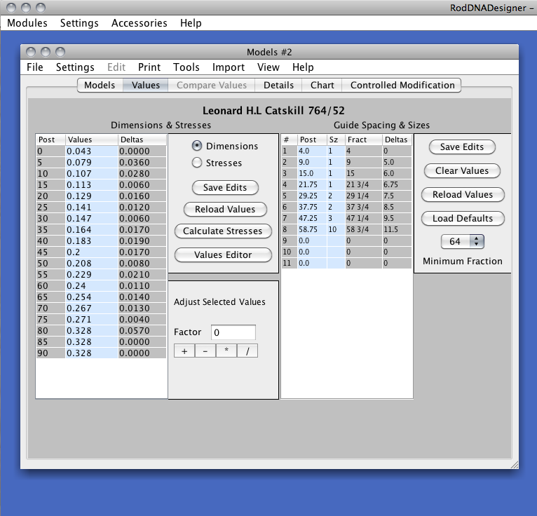
The Values Tab is used to view/enter/edit the Dimension and/or Stress values for the selected Model. You can also edit the guide information. Once you modify the values, you can either save them or reload the initial values from the associated Model. You need only enter Dimensions and RodDNADesigner will automatically calculate the corresponding stresses. The number of values will correspond to the Model’s Action Length (ActLngInch) divided by the Station Increment (StationIncr). I recommend using 5" Station Increments as this corresponds to most planning forms, and minimizes the number of dimensions that have to be entered. Note that the Station Increment will also determine the increments on the Planing Report.
The Values Tab is also used to view/enter/edit the Guide Spacing and Size values for the selected Model. Once you modify the values, you can either save them or reload the initial values from the associated Model. You don't need to enter any values unless you want to change the default spacings and/or sizes (see Guide Settings). The number of values will correspond to the Model’s Rod Length (LengthInch) divided by 12 + 2.
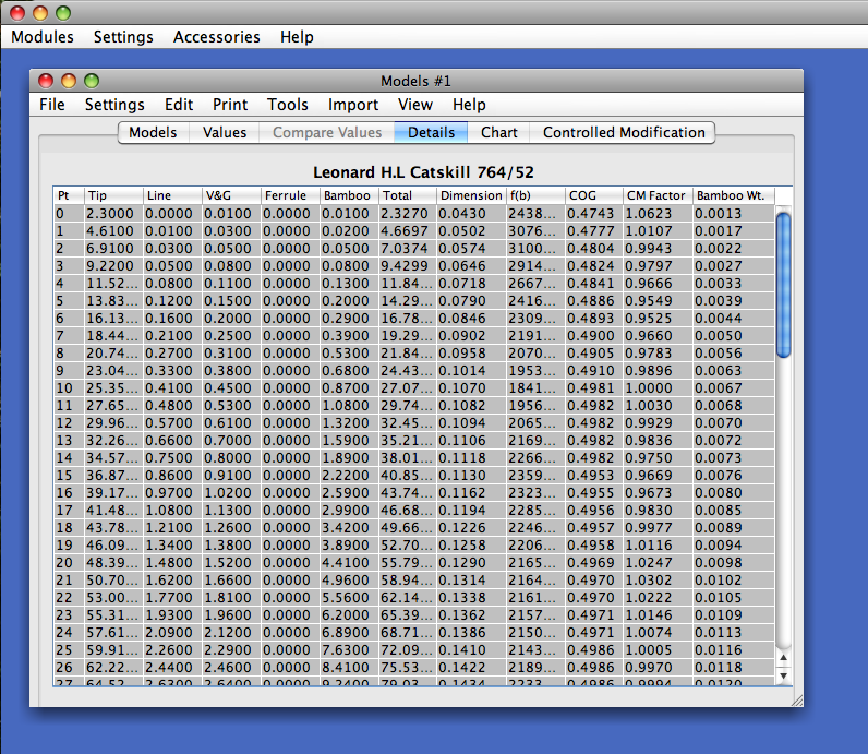
The Details Tab is used to view the intermediate static stress calculations, and is for reference only. Note that if the title reads Details+, the values will reflect the Controlled Modification calculations, and will show the resultant dimensions (Dimension) and factors (CM Factors).
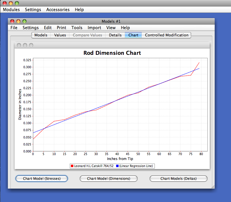
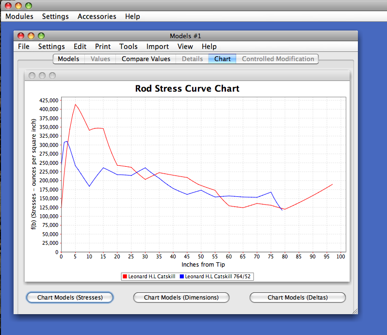
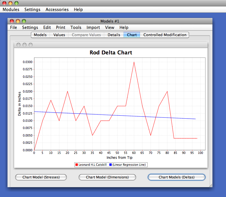
The Chart Tab is used to view the dimension, stress and delta charts. You can select which chart to render using the Chart buttons located at the bottom of the dialog.
You can zoom-in by placing the cross-hairs on a location and dragging them while holding the left mouse-button.
Various options are available by a single click on the right mouse button:
|
Properties |
allows you to specify colors, fonts, etc. |
|
Save As |
allows you to save your rendered chart as a ".PNG" image file for you documentation. |
|
|
allows you to print your rendered chart (you might want to select Landscape mode) |
|
Zoom In |
allows you to zoom in (either or both axis) |
|
Zoom Out |
allows you to zoom out (either or both axis) |
|
Auto Range |
allows you to change either axis’s back to the original values while leaving the other as zoomed |
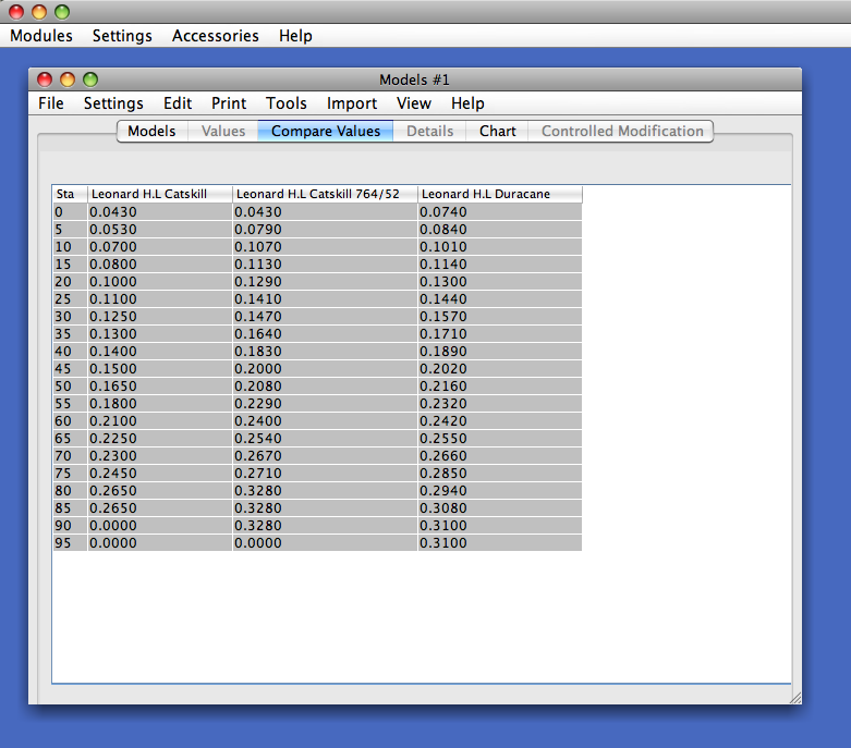
The Compare Values Tab is used to visually compare the selected Models taper values.
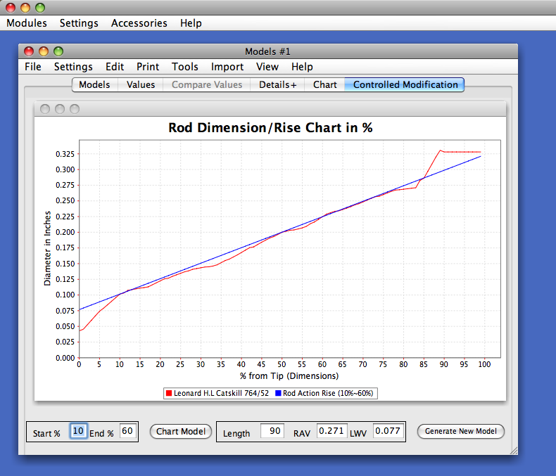
The Controlled Modification Tab provides access to my implementation of John Bokstrom's "Rod Design by Controlled Modification". Any selected Model can be modified to suit your own requirements of length, action, or line size. Fine adjustments are possible to tailor a rod to your precise personal preferences.
The Controlled Modification Dialog charts the selected Model's taper dimensions and rise in percentages vs. inches from the tip of the rod. The start and end of the rod's action curve are preset to 10% and 60% respectively, but can be changes and re-charted by clicking on the Chart Model button. Once charted, you can create a new Model after you select the new Model's Rod Length (Length), Rod Action Value (RAV) and Line Weight Value (LWV).
Because individual building techniques such as tempering, glue, etc. affect the end results, and because rod actions and line sizes are subjective judgments, it is suggested that the first rod built from this program not deviate too much from the original. This will assure a very usable rod and help develop confidence in future changes.
If you like the selected Model but want a longer or shorter version, simply edit the Length value and click on the Create New Model button.
The RAV (Rod Action Value) determines the action of the rod. Increasing this value makes the rod action faster, decreasing it makes the rod slower. A change of .003 is detectable, providing the rods are built in the same manner, while a change of .010 is definitely noticeable.
The LWV (Line Weight Value) determines the line size. An increase or decrease of .004 to .006 will raise or lower the line size by one line weight but finer adjustments can be made if desired. Since judgment of line size is subjective, no definitive values can be given.
There is a practical minimum diameter for the actual tip of a rod and, although this is already compensated for in the programs, it may be necessary to adjust the 0" diameter to not less than .0625 if designing a very light rod. See page 272 of the Garrison book.
You may note that the value of the slope rise lines at point 0 reflects the line weight. For example, ~.072 = 5wt, ~.078 = 6wt, ~.084 = 7wt, ~.088 = 8wt, ~.094 = 9wt, etc.
Models Menus
File Menu
Unlike the Designs Module, the Models Module utilizes Files containing one or more Models. You can have as many Model files as you desire. When you select the Models Module, it will try to load the Models file whose name is contained the preference setting. You can modify this setting to specify you own Models file.
The main Models file is called RodDNAModels.rdm and contains hundreds of Models.
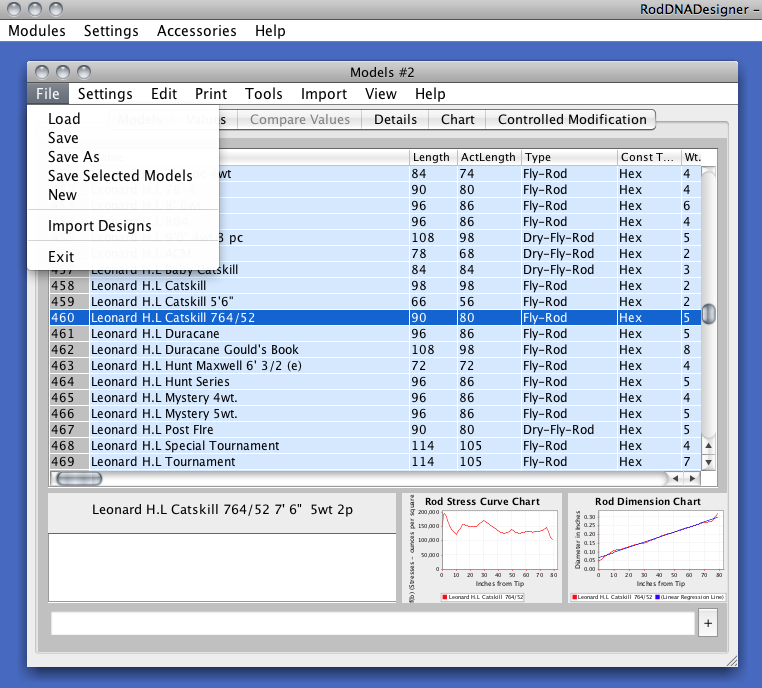
The File menu allows you to do the following:
Load - Loads or opens a particular Model file.
Save - Saves your current Models file.
Save as - Similar as Save but allows you to rename the Models file.
Save Selected Models - Used to save any selected Models in a new Models file.
New - Used to create a new, empty Models file. You can then select append from the Edit menu to create new Models.
Import Designs - Used to import one or more existing Design files as Models. This is only way you can create Models from Designs.
Exit - will exit the Models dialog.
Edit Menu
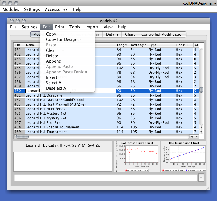
The Edit menu allows you to manipulate Models contained in a Model file that are loaded in your computer's memory.
Note that if you inadvertently delete or modify a Model, just exit the Models Module without saving the changes. This will not modify the Models file. Once you save the file with your changes the previous contents are overwritten.
A good practice is to save your changes to different Model files.
The Edit menu allows you to do the following:
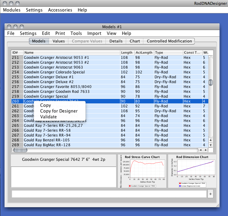
Copy - Copies the selected Model or Models.
Copy for Designer - Copies the selected Model or Models for use with the Designer Module.
Paste - Will paste the selected Model or Models that you previously Copied OVER the selected Model or Models.
Clear - Will reset the selected Model or Models to the Model default values.
Delete - Will delete the selected Model or Models.
Append - Will append a new default Model to the bottom of the Models list.
Append Paste - Will append the selected Model or Models to the bottom of the Models list.
Append Paste Design - Will append the selected Design from the Designer Module to the bottom of the Models list.
Insert - Will insert a default Model before the first selected Model.
Select All - Will select all the Models.
Deselect All - Will de-select all the Models.
Note that if you right-click on a selected Model or Models you can access the Edit Copy functions and also quickly validate a Model.
Settings Menu
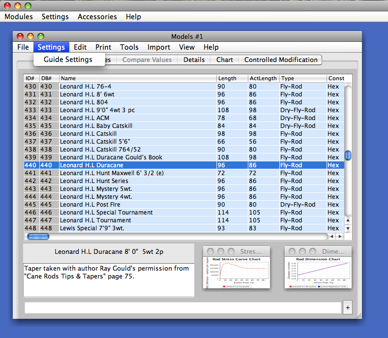
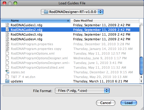
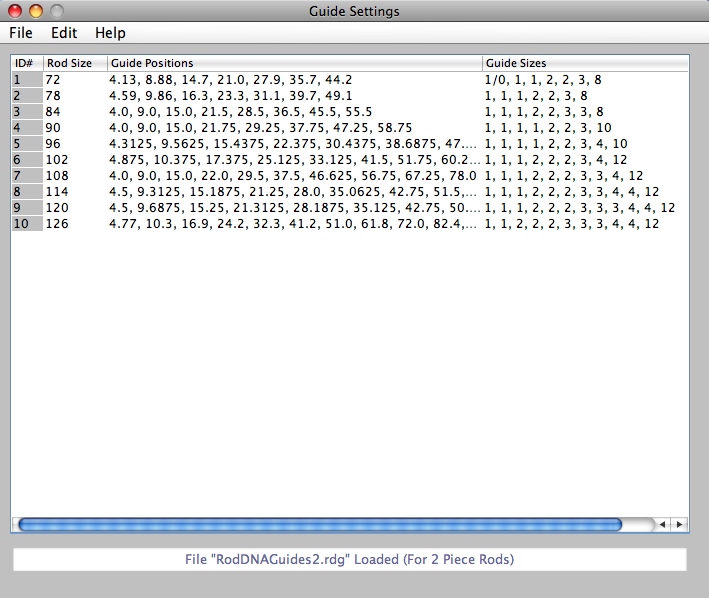
RodDNADesigner can set the default guide locations and guide sizes automatically. Rather than calculate the positions, four files are used to determine the guide locations and sizes, one for 1 through 4 piece rods. When you select the Guide Settings from the Settings Menu, you select which of the four files you would like to view or edit. The number of pieces is indicated in the file name ending. Note that Rod Sizes must be in ascending order, and can be copied and pasted if needed. Also, the # of Guide Positions must match the # of Guide Sizes.
RodDNADesigner uses the rod's # pieces to determine which guide file to load, then uses the Rod Size (or the closest matching entry) for the values. The Stripper size is determined by the line weight. for weights 2, 3 & 4 the size is #8. For weights 4 & 5 the size is #10. For weights 6 through 9 the size is #12, and above 9 is a #14. These are only default values, and can be edited and saved for each Model.
Print Menu
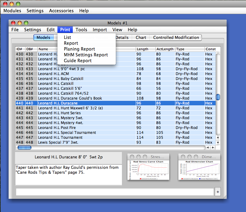
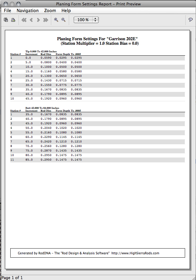
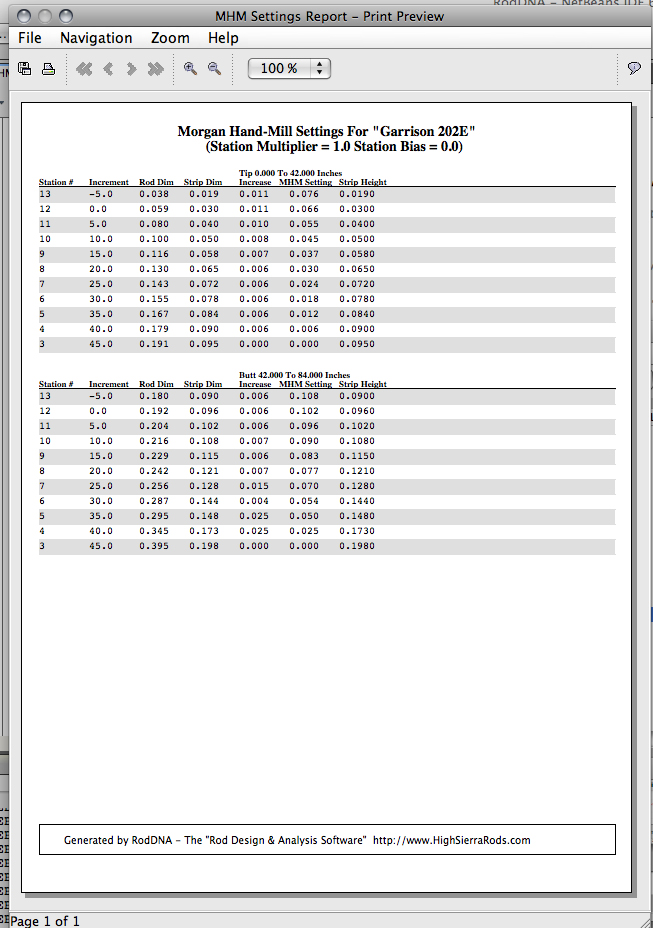
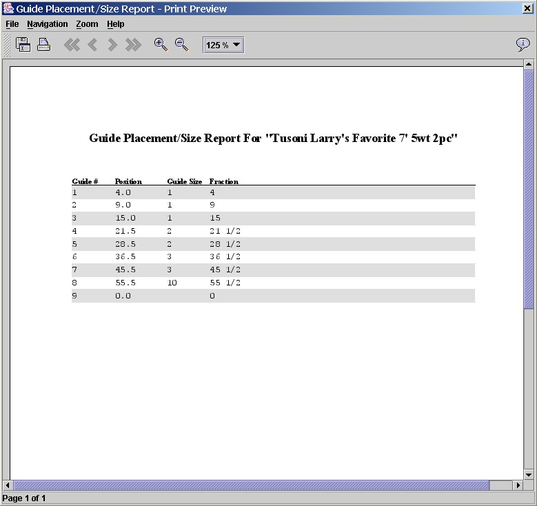
The Print menu provides a List report which will print one-line per Model selected, or a one-page Report per Model selected. The Planing report will print a combined metric/inch planning report for the selected Model (it has been designed to be folded in half vertically). Note that the planing report using the station increment defined in the Program Options file Planing Report Station Increment Range option and not the Models station increment. This allows the Model's dimensions to be specified in different increments vs. the planing forms actual station increments. The Guide Report will print a report for a selected Model containing guide #, guide position in inches, guide size and guide position in fractions for easy measurements. The Morgan Hand-Mill settings report will produce a report of the necessary settings for your hand-mill for any selected Model. Note that Form Depth is provided for you convenience.
Tools Menu
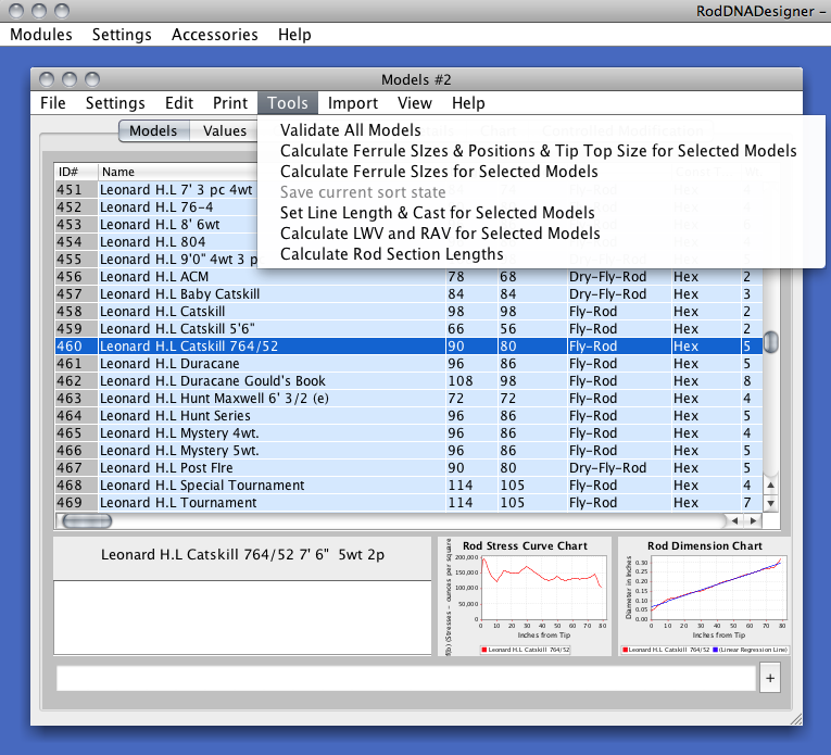
This Tools menu provided an option to validate all existing Models which can be automatically run via the Validation Method selection in the Programs Options. Note: you can validate any Model by right-clicking on any column, which is useful when you create a new Model and want to quickly validate it.
Ferrule sizes/positions and Tip top sizes can be automatically calculated also by selecting which models you would like then selecting the Calculate Ferrule Sizes & Positions & Tip Top Size option. Note use Calculate Ferrule Size for rods with different length sections.
If your list of Models is sorted, you can use the Tools menu selection Save current sort state to save the sorted Models list in memory. Use the File menu options to save it permanently.
You can automatically have the Line Length and Line Cast Length set for selected models by the menu selection by that name. Note that the line weight is used to determine the Line Cast Length. This is important for correct Stress calculations.
The Calculate LWV and RAV menu selection utilizes the Controlled Modification component to generate the LWV (Line Weight Value) and the RAV (Rod Action Value) for the selected Models. This is useful for comparing different Models. Note that you can sort on either value for easier comparisons.
The Calculate Rod Section Lengths selection will automatically calculate the rod section lengths. All you need to enter are the male-ferrule cap thickness, the male-ferrule slide length and the reel-seat butt cap thickness.
Import Menu
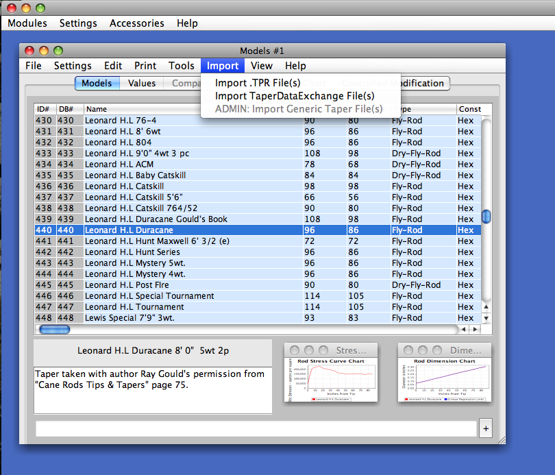
The Import Menu allows you to quickly load any existing Model information that you may have previously saved in other file formats. One or more files can be selected at a time.
Since each file type contains different data, you should check each Model’s data once imported by running the validation function and by visually checking it.
Currently, taper files (files suffixed with .tpr) can be directly imported via the Import .TPR File(s) selection. Each taper file contains one Rod taper or Model, and it’s values will be appended to the end of your existing Model list.
Current Taper Data Exchange files can also be imported via the ImportTaperDataExchange File(s) selection. Note that the import file should be created using tabs as the field separator, including header record with field names (do not enclose fields in double quotation marks.)
View Menu
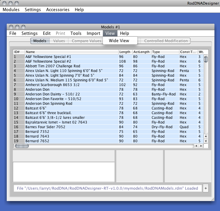
The View Menu provided a narrow or wide view. Note the the + button on the bottom right of the Models Module will toggle between a normal and large font.
Help Menu
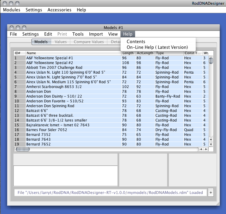
The Contents selection will link to the installed web pages on your computer.
The On-Line selection will link to the latest web pages located on the RodDNADesigner server, so you will have to be connected to the Internet to view it.
Automatically Generated Models
New discreet Models may be automatically generated when certain fields are modified. For example, if you change the Construction Type (Const Type) from Hex to Quad, you will have the option to let RodDNADesigner generate a new Model in which the dimensions will be converted for the Quad rod. You can convert from Hex to Quad or Penta, and from Quad to Hex. Note that the stresses are used for automatic conversions for: line weight changes, # pieces changes and geometry changes. Using this technique the resulting Model will have the same feel or action as the original.
Also, if you change the # of pieces, the line weight or the geometry, you will have the option to let RodDNADesigner generate a new Model in which the dimensions will will reflect the same stresses as the original rod, and therefore the same action, or if you select to not generate a new model, the change will be reflected in the existing Model.
The other way to let RodDNADesigner generate a new Model is when you use the Controlled Modification feature previously mentioned.
Release Notes
This is the initial release of RodDNADesigner v 1.0. Release notes will be updated as necessary.
Future Releases
I have quite a few more features planned for future releases, so please let me know if you have any feature ideas that I should also implement.
Support
If you have any questions or issues please email support@RodDNA.com. Please include the issue and a call-back phone number.
Other Sources of Information
If There is a users mailing list where you can find useful information about RodDNADesigner issues. Here is the URL:
Credits
I would like to thank everyone, especially Chris Bogart and Philipp Sicher for their help with this release and to all those who contributed tapers.
RodDNADesigner contains an deflection implementation developed with help from Al Baldauski.RodDNADesigner contains an implementation of John Bokstom's "Fly Rod Design by Controlled Modification", and is used by permission.
RodDNADesigner also contains an implementation of Mr.
Garrison's Stress calculation formulas from Chapter 14 of "The Book".
Larry Tusoni / High Sierra Rod Company
Angels Camp & Virginia Lakes, California
1 January 2011
larry@HighSierraRods.com
http://www.HighSierraRods.com
Java, Sun and Solaris are trademarks of Sun Microsystems, Inc.
Windows is a trademark of Microsoft Corporation.
Macintosh is a trademark of Apple Corporation.
Copyright © 2003~2011 Larry Tusoni / High Sierra Rod Company. All rights reserved.